The previous article dealt with a dangerous and unfortunately common mistake, namely "island grounding" (link).
Let's now look at how to do it right.
Safety is not provided by an individual device, but by the grounding system of the object as a whole. The correct design of such systems are described in standards and textbooks. The main variants are designated as follows: TN-S, TN-C, TN-C-S, TT and IT.
The IT variant is used in special cases. For example, in operating theatres where it is necessary to have a guarantee that even microampere leaks do not occur, since even such currents are dangerous in contact with an open heart.
The TT system is suitable for small objects such as a summerhouse, especially if it is connected by a very long power line.
TN-C, TN-S and TN-C-S are the most common. Their common name is "dead-grounded neutral systems." Electricians like to use scary words.
In these systems, the equipment enclosures are connected to the supplying transformer or generator (in the case of the generator, all positions remain exactly the same). But they are connected with neutral lead that is securely connected to the ground.
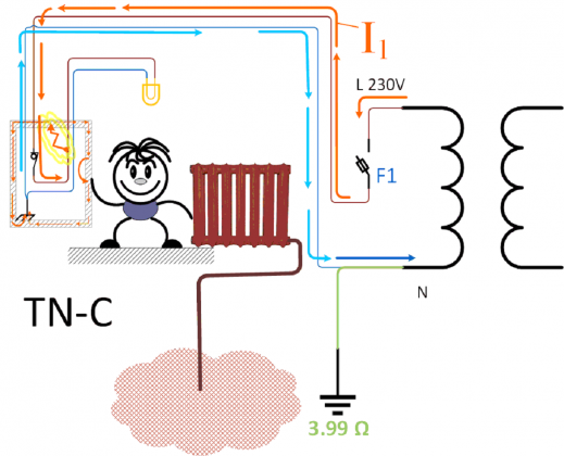
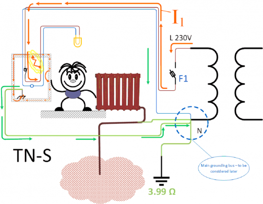
This diagram shows the now obsolete but still used TN-C system. In it, the same conductor carries both the operating "neutral" current and the emergency "overcurrent" phase-to-chassis fault. The conductivity of this conductor (called PEN = PE+N, i.e. protective earth + neutral) is much better than that of the earthing conductor (milli-ohms versus ohms). The I1 current rises to thousands of amps for a short time, which causes the F1 protection to trip almost instantly.
Incidentally, the chassis voltage does not rise to 230V even during those milliseconds, because such a current "saturates" the transformer, which leads to a large voltage drop.
It is easy to see that this system has a big disadvantage. If the neutral conductor burns out, things get very bad at once.
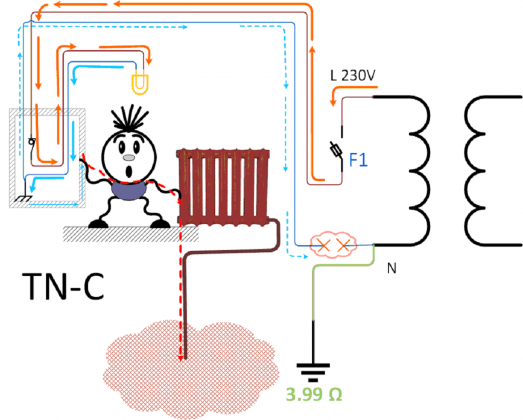
Without any short circuit, "through the bulb", the box gets a 230V potential. And on all appliances in this segment of the wiring.
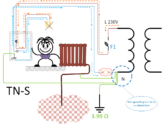
To overcome this disadvantage, the TN-S (S=separate) system was introduced. This system uses separate conductors for protection, through which no appreciable current flows under normal conditions. Therefore, it is much less likely that they will burn out or suffer electrochemical corrosion. In addition, the conductors of this system can be disconnected from each other with minimum precautions for test measurements (disconnecting the operating zero is only permissible when the facility is de-energized).
The cross-section of a single protective conductor must be equal to the phase cross-section for this section of the network. Justified by a special design calculation it can be reduced to half of the phase conductor, but no more.
This diagram shows break of neutral in a TN-S system. In fact, neutral breaking is a very unpleasant accident, especially in a three-phase network. Overvoltages due to phase imbalance can damage equipment. But there is no direct threat to human safety.
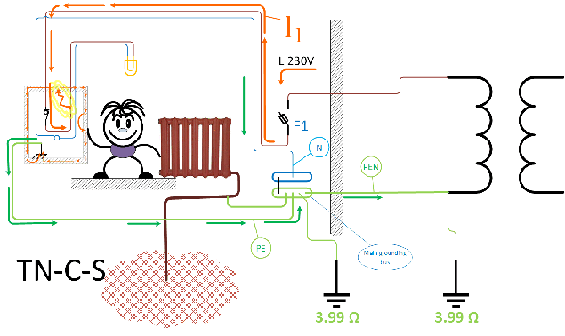
In real life, new buildings often features combination of these systems TN-C-S. A single PEN conductor is laid from the transformer to the main switchboard of the building. In this part of the circuit, the wire cross-sections are usually large, so the reliability of the combined conductor is sufficient. And the distance from the transformer to the building can be considerable. Therefore, the savings are substantial. To prevent severe consequences in case of a PEN break, a re-earthing to the earth electrode next to the building is performed. For such a re-earthing, a cross-section of 25 mm2 is sufficient, just because the current is limited by the resistance of the earth electrode.
We have considered the general ideas of systems with a dead earthed neutral. Each real object has its own important features. To be sure of the correct implementation of the system at a particular site, it is best to contact qualified professionals.


